With this tool, you can calculate the angle of twist of a member subjected to a torque by inputting the variables of the angle of twist formula (shaft length, torque, polar moment of inertia, and shear modulus).
Although the deformations in power transmission shafts are relatively small, an excess of them may cause vibration problems, resulting in noise and improper synchronization. Additionally, they can cause significant displacements in larger members connected to them (e.g., gears) because of the radial distance of those members (see the angular displacement formula).
For these and other reasons, it's necessary to study the relationship between torque and angle of twist and the equation behind it.
The formula for angle of twist calculation
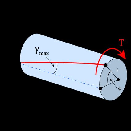
Succinctly, the angle of twist is the relative rotation of one face of a shaft with respect to another face when a torque is applied to that shaft. The angle of twist of one end of a shaft with respect to the other end is given by:
In the previous equation:
- — Angle of twist (calculated in radians);
- — Internal torque;
- — Shaft length;
- — Polar moment of inertia; and
- — Shear modulus of the shaft material.
The shear modulus and the polar moment of inertia represent the material's reluctance to twist or suffer a shear strain (in fact, shear strain is related to through the shear strain equation). While the shear modulus is a material property, the polar moment is a geometric property that depends on the shaft cross-section.
For a solid circular shaft of diameter , the polar moment of inertia equals . On the other hand, for a hollow circular shaft with an internal diameter , it equals . For non-circular shafts, the angle of twist equation also holds, but we must use something known as the torsional constant instead of the polar moment. You can learn more about them in the polar moment of inertia and torsional constant calculators.
The angle of twist equation is not a catch-all formula, as it works under certain assumptions:
- The member (a shaft, usually) is straight, and its cross-section is uniform or invariable;
- Along its length , the member experiences the same internal torque ; and
- The material is homogeneous and behaves in a linear elastic way along the length .
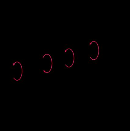
For example, in the image below, the torque and cross-section are constant along the whole member. If the material is homogenous and behaves according to Hooke's law, we can use the angle of twist formula.
Jump to this section to know what to do if the assumptions are unmet.
The angle of twist units
Our calculator will give you the correct result regardless of the input units. Even so, to use the angle of twist equation, we must warranty dimensional homogeneity between the different variables.
To achieve that homogeneity in the International System of Units (SI system) and the United States Customary Units System (USCS), use the following units:
SI system | USCS | |
|---|---|---|
radian (rad) | radian (rad) | |
newton-meter (N·m) | pound-inch (lbf·in) | |
meter (m) | inch (in) | |
meter to the 4th power (m⁴) | inch to the 4th power (in⁴) | |
pascal (Pa) | pound-force per square inch (lbf/in²) |
The resulting angle of twist using the formula will always be in radians, no matter if we use USCS or the SI system. You can convert it to degrees remembering that or using our radians to degrees converter.
The angle of twist equation for variable torque, material, or radius
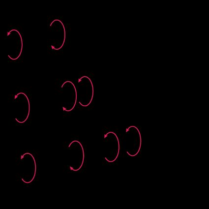
If the torque, cross-section, or material change along the shaft, we can also calculate the angle of twist by slightly modifying the equation. The modification consists of applying the equation separately to each shaft portion in which the three quantities remain constant and then summing the angle of each part:
As those quantities vary, the twist angles will do the same, and it could even change in sign (positive angle in one direction, negative in the other). The direction and sign of the angle will equal that of the internal torque, which we obtain by using the method of sections and the equations of moment equilibrium learned in statics.
We must establish a sign convention to deal with the fact that and can vary in sign. The sign convention consists of applying the right-hand rule, taking as positive the torques in the counterclockwise direction or whose vector direction points away from the sectioned end.
For example, let's calculate the angle of twist of point A relative to D in the following shaft made of a Malleable ASTM A-197 cast iron alloy . The shaft diameter is .
Considering the mentioned sign convention, let's apply the method of sections to the different segments of the shaft and draw a torque diagram.

Before calculating the angle of twist, let's obtain the polar moment of inertia:
Finally, we can apply the modified angle of twist formula, considering the different signs of the internal torque:
If, instead, we want to calculate the angle of twist of point A relative to C, we do almost the same, ignoring the portion that goes beyond C:
The previous example applied to cases where the torque suddenly changed across the shaft, but, of course, we can follow the same procedure whenever we find an abrupt change in or .
Shear modulus of typical engineering materials
If you don't know the shear modulus of the shaft material, you'll probably find it in the following list (scroll to the right of the table to look at the values):
Material | Shear modulus G | |
|---|---|---|
Aluminum wrought alloys | 2014-T6 | 27 GPa (3.9 × 10⁶ psi) |
6061-T6 | 26 GPa (3.8 × 10⁶ psi) | |
Cast iron alloys | Gray ASTM 20 | 27 GPa (3.9 × 10⁶ psi) |
Malleable ASTM A-197 | 68 GPa (9.9 × 10⁶ psi) | |
Copper alloys | Red Brass C83400 | 37 GPa (5.4 × 10⁶ psi) |
Bronze C86100 | 38 GPa (5.5 × 10⁶ psi) | |
Magnesium alloy | Am 1004-T61 | 18 GPa (2.6 × 10⁶ psi) |
Steel alloys | Structural A-36 | 75 GPa (10.9 × 10⁶ psi) |
Structural A992 | ||
Stainless 304 | ||
Tool L2 | ||
Titanium alloy | Ti-6Al-4V | 44 GPa (6.4 × 10⁶ psi) |
FAQs
What is the relationship between torque and angle of twist?
The following formula gives the relationship between torque and the angle of twist:
ϕ = TL/JG
where:
- ϕ — Angle of twist (calculated in radians);
- T — Internal torque;
- L — Shaft length;
- J — Polar moment of inertia; and
- G — Shear modulus of the shaft material.
That equation is valid for constant cross-section circular shafts made of a homogenous linear elastic material subjected to an invariable internal torque.
What does the torque vs. angle of twist graph say?
The torque vs. angle of twist graph indicates mainly two things:
-
The linear part shows the torques and angles for which the specimen behaves in a linear elastic way.
-
From the linear part, we can take one "torque vs. angle" point and obtain the modulus of rigidity through the formula G = TL/Jϕ. We can even take various points and average them to get a more reliable value.
What is the angle of twist unit?
The angle of twist units commonly used are the radian (rad) and, to a lesser extent, degrees (°). The angle of twist formula result is always in radians, and to convert it to degrees, use the following formula degrees = radians × 180°/π.
How to know the maximum angle of twist before yielding starts?
To obtain the maximum angle of twist before the onset of yielding:
-
Calculate the maximum elastic torque (TY):
TY = (π/2)(τYc³)
where τY is the shear yield point, and c is the shaft radius.
-
Once you know TY, simply input it in the angle of twist formula to obtain the maximum angle: ϕ = TYL/JG.
What is the angle of twist of a 3 m long and 100 mm diameter solid aluminum bar (G = 80 GPa) experiencing a 10 kN·m torque?
2.19 degrees (°). To calculate the angle of twist in this case:
-
Obtain the polar moment of inertia. For a solid circular bar:
J = (π/32)D⁴ = (π/32)(0.100 m)⁴ = 0.000009817 m⁴
-
Use the angle of twist formula:
ϕ = TL/JG
ϕ = (10000 N·m × 3 m)/(0.000009817 m⁴ × 80×10⁹ Pa)
ϕ = 0.0382 rad = 2.19°