
This RLC impedance calculator will help you to determine the impedance formula for RLC, phase difference, and Q of RLC circuit for a given sinusoidal signal frequency. You only need to know the resistance, the inductance, and the capacitance values connected in series or parallel.
You can interpret the name 'RLC circuit' to mean a circuit consisting of a resistor, inductor, and capacitor connected in series or parallel. Today, it is hard to imagine the world of electronics without the use of RLC circuits. You have undoubtedly encountered them in everyday life, as they are very commonly used in radio receivers and televisions or attenuator circuits in analog applications.
With this calculator, you will quickly learn:
- What an RLC circuit is;
- How to calculate impedance in an RLC circuit;
- What is the resonant frequency of an RLC circuit; and
- What a phase angle is in an RLC circuit.
What is an RLC circuit?
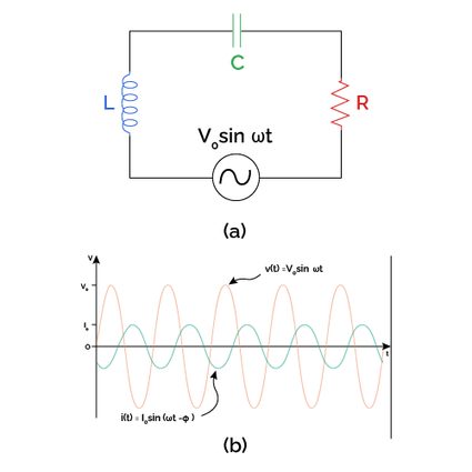
An RLC circuit (or LCR circuit, we can change the order of the letters) consists of resistance (), inductance (), and capacitance () connected in series or parallel.
Series connection means that all elements are located behind each other when connected to AC, and the same current flows through each of them.
In a parallel RLC circuit, a resistor, an inductor, and a capacitor are connected in parallel via a supply voltage, and the applied voltage remains the same across all components while the current is divided.
When an AC is connected to an RLC circuit, the charging and discharging of the capacitor are repeated cyclically, leading to oscillation. Energy losses in the form of heat release cause the oscillation to stop after some time. Visit our damping ratio calculator to learn how the oscillations disappear.
Resonant frequency of RLC circuit
The resonant frequency in an RLC circuit is the so-called natural frequency of the RLC circuit. What does this mean? If we supply an electrical charge to a capacitor, the circuit starts to oscillate at precisely the frequency determined above.
The resonant frequency can be calculated in our resonant frequency calculator or determined from the formula:
At the resonant frequency, the impedance of the series RLC circuit is minimum. When we connect the resistor, inductor, and capacitor in parallel, the impedance of the circuit becomes maximum.
How to calculate impedance of RLC circuit?
The impedance of an RLC circuit is denoted as and plays an analogous role to the resistance in Ohm's law formula. The impedance of an RLC circuit creates resistance to current flow because of the presence of the resistor , the inductor , and the capacitor . The SI unit of impedance is Ohm (Ω).
RLC impedance calculator uses the following impedance formula for an RLC circuit in a series:
where:
- — Resistance;
- — Inductance;
- — Capacitance, and
- — Angular frequency .
If you want to know how to calculate impedance in a parallel RLC circuit, use this equation:
Phase angle in RLC circuit
The phase difference is the angle (in degrees or radians) by which the voltage applied to an RLC circuit delays or leads the resulting current.
If the phase difference is positive, the applied voltage leads the resulting current.
If the phase difference is negative, the applied voltage lags the resulting current.
Since current and voltage are sinusoidal, you can compare them in our phase shift calculator.
You can also calculate phase difference in a series RLC circuit from the formula:
Modify the formula to calculate phase difference in a parallel RLC circuit:
Q factor of an RLC circuit
The Q-factor or quality factor determines the quality of an RLC circuit. When you design an RLC circuit, you should aim for the highest possible Q-factor. The formula for the is as follows:
FAQs
What is an RLC circuit?
An RLC circuit consists of a resistor R, an inductor L, and a capacitor C. You can find it in many configurations of connecting the components, but the most common are in series or in parallel. There are cyclic oscillations in the RLC circuit damped by the presence of the resistor.
How can I calculate impedance in an RLC circuit?
To calculate impedance in an RLC circuit follow these steps:
-
Determine whether the circuit is in series or parallel.
-
Measure the resistance
Rusing the multimeter. -
Find the inductance
L. -
Measure the capacitance
C. -
Define the frequency of the circuit
f. -
Evaluate angular frequency:
ω = 2πf -
Calculate the impedance of the series RLC circuit from the formula:
Z = √(R²+(ωL-1/ωC)²) -
Find the impedance of the parallel RLC circuit:
Z = 1/√(1/R² + (1/ωL - ωC)²)
What is the impedance of an RLC circuit?
Impedance describes the properties of an RLC circuit in resisting the flow of current. Note that it sounds similar to resistance, but impedance changes proportionally to frequency. RLC circuits are often used as examples for basic impedance analysis.
Does impedance of an RLC circuit depend on resistance?
Yes. Impedance is the combination of resistance and contribution from a capacitor, an inductor, or a combination of both. At the resonant frequency, the two contributions cancel each other out, and the total impedance of the series circuit becomes just the value of the resistance.
What is the impedance of a parallel RLC circuit at 1 kHz?
If you have a 10 Ω resistor, 2 mH inductor, and 500 μF capacitor, the impedance is 0.326 Ω. Here's how this result was calculated:
-
Use the impedance of the parallel RLC circuit formula:
Z = 1/√(1/R² + (1/(ωL) - ωC)²) = 1/√(1/R² + (1/(2πfL) - 2πfC)²) -
Enter the
R = 10 Ω,L = 2 mH,C = 500 μF, andf = 1 kHz:Z = 1/√(1/10 Ω² + (1/(2π × 1000 Hz × 0.002 H) - 2π × 1000 Hz × 0.5 F)²) = 0.326 Ω