
This beam deflection calculator will help you determine the maximum beam deflection of simply-supported and cantilever beams carrying simple load configurations.
You can choose from a selection of load types that can act on any length of beam you want. The magnitude and location of these loads affect how much the beam bends.
In this beam deflection calculator, you'll learn about the different beam deflection formulas used to calculate simply-supported beam deflections and cantilever beam deflections. You will also learn how the beam's modulus of elasticity and its cross-sectional area moment of inertia affect the calculated maximum beam deflection.
Beam deflection is an important part of beam analysis, but another important part is stress analysis. The section modulus is a powerful tool to study beam bending stresses, which you can calculate using our section modulus calculator, or go straight to our bending stress calculator for the maximum stress a beam experiences directly.
What is beam deflection and beam bending?

In building construction, we usually use framing structures that are held in place by the foundations in the ground. These framing structures are like the skeletons of buildings, houses, and even bridges. In a frame, we call the vertical framing columns and the horizontal ones beams. Beams are the extended members of a structure that carry the loads brought by the horizontal slabs of the structures like solid concrete floors, wooden floor joist systems, and roofs.
When beams carry loads too heavy for them, they start to bend. We call the amount of beam bending beam deflection. Beam deflection is the vertical displacement of a point along the centroid of a beam. We can also consider the beam's surface as our reference point as long as there are no changes in the beam's height or depth during the bending.
How to calculate the maximum beam deflection
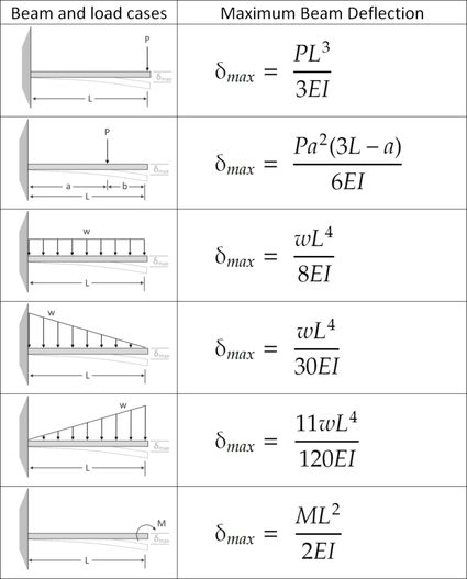
We equipped our beam deflection calculator with the formulas that engineers and engineering students use to quickly determine the maximum deflection a specific beam will experience due to the load it carries. However, these formulas can only solve simple loads and a combination of these loads. We have tabulated these formulas for you, as shown below:
Simply-supported beam deflection formulas
Beam and load cases | Maximum beam deflection equation () |
|---|---|
 | |
 | |
If | |
 | |
 | |
 | |
 |
Cantilever beam deflection formulas
Method of superposition
To calculate the maximum deflection of a beam with a combination of loads, we can use the method of superposition. The superposition method states that we can approximate a beam's total deflection by adding together all the deflections brought about by each load configuration. However, this method only gives us an approximate value for the actual maximum deflection. Calculating complicated loads would require us to use what is known as the double integration method.
Flexural rigidity of the beam
Calculating beam deflection requires knowing the beam's bending or flexural rigidity and the amount of force or load that would influence its bending. We can define the beam's flexural rigidity by multiplying its modulus of elasticity, E, by its area moment of inertia, I.
The modulus of elasticity depends on the beam's material. The higher a material's modulus of elasticity, the more of a deflection can sustain enormous loads before it reaches its breaking point. Concrete's modulus of elasticity is between 15-50 GPa (gigapascals), while steel tends to be around 200 GPa and above. This difference in the values of modulus of elasticity shows that concrete can only withstand a small amount of deflection and will experience cracking sooner than steel.
You can learn more about the modulus of elasticity by checking out our stress calculator. On the other hand, to determine the area moment of inertia for a particular beam cross-section, you can visit our moment of inertia calculator. The area moment of inertia represents the amount of resistance a material has to rotational motion. The area moment of inertia depends on the dimensions of the material's cross-section.
The area moment of inertia also varies depending on which axis the material is rotating along. To further understand this concept, let us consider the cross-section of a rectangular beam with a width of 20 cm and a height of 30 cm. Using the formulas that you can also see in our area moment of inertia calculator, we can calculate the values for the area moment of inertia of this beam cross-section as follows:
Iₓ = width × height³ / 12
Iₓ = 20 × (30³)/12
Iₓ = 45,000 cm⁴
Iᵧ = height × width³ / 12
Iᵧ = 30 × (20³)/12
Iᵧ = 20,000 cm⁴
Notice how there are two values for the area moment of inertia. That's because we can consider the beam to bend vertically along the beam span (or experience a bending moment around the x-axis) and laterally along the beam span (or bend around the y-axis). Since we are considering the deflection of the beam when it bends vertically or around the x-axis, we have to use Iₓ for our computations.
The area moment of inertia values we obtained tell us that the beam is harder to bend with a vertical load and easier to bend if subjected to a horizontal lateral load. This difference in the area moment of inertia values is why we see beams in this configuration, wherein their height is greater than their width.
Understanding the beam deflection formulas
Now that we know the concepts of modulus of elasticity and area moment of inertia, we can understand why these variables are the denominators in our beam deflection formulas. The formulas show that the more rigid the beam is, the smaller its deflection will be. However, by inspecting our formulas, we can also say that the beam's length also directly affects the deflection of the beam. The longer the beam gets, the more it can bend and the greater the deflection.
Loads, on the other hand, affect the beam's deflection in two ways: the direction of the deflection and the magnitude of the deflection. Downward loads tend to deflect the beam downwards. Loads can be in the form of a single-point load, linear pressure, or moment load. The formulas in this calculator only focus on either the downward or upward directions for the point load and distributed loads. Distributed loads are similar to pressure but only consider the beam's length and not the beam's width.
The formulas in this calculator also consider the moment or torque load, either clockwise or counterclockwise. To figure out which direction has a positive load value, consult the directions of the arrows in the formula's corresponding image.
Sample beam deflection calculation

For a sample calculation of beam deflection, let us consider a simple wooden bench with legs 1.5 meters apart from each other at their centers. Let us say we have a 4-cm thick, 30-cm wide eastern white pine plank that acts as the seat for this bench. We can consider this seat as a beam that will deflect whenever someone sits on the bench. Given the dimensions of this seat, we can then calculate its area moment of inertia, similar to our example above. Since we need to calculate Iₓ, its area moment of inertia would be:
Iₓ = width × height³ / 12
Iₓ = 30 × (4³)/12
Iₓ = 160.0 cm⁴ or 1.6×10⁻⁶ m⁴
Eastern white pine has a modulus of elasticity of 6,800 MPa (6.8×10⁹ Pa), which is the value we obtained from the . You can also easily obtain the value of the modulus of elasticity for other materials, such as steel and concrete, from the internet or your local library. Now that we know these values, let us consider the load this bench will carry. Suppose a 400 N child sits in the middle of the bench. We can now calculate the deflection the bench's seat will experience due to a point load at its center:
δmax = P × L³ / (48 × E × I)
δmax = (400 N) × (1.5 m)³ / (48 × 6.8×10⁹ Pa × 1.6×10⁻⁶ m⁴)
δmax = 0.002585 m = 2.5850 mm
This means that the bench seat will sag around 2.6 millimeters from its original position when the child sits in the middle of the bench.
If you found this topic interesting and would love to learn more about the strength of materials, you might also like our factor safety calculator.
FAQs
What is deflection in engineering?
Deflection in engineering refers to the movement of a beam relative to its original position. This movement can come from engineering forces, either from the member itself or from an external source such as the weight of the walls or roof. Deflection in engineering is a measurement of length because when you calculate the deflection of a beam, you get an angle or distance that relates to the distance of the beam's movement.
What is the general formula for beam deflection?
The general formulas for beam deflection are PL³/(3EI) for cantilever beams, and 5wL⁴/(384EI) for simply-supported beams, where P is point load, L is beam length, E represents the modulus of elasticity, and I refers to the area moment of inertia. However, many other deflection formulas allow users to measure different types of beams and deflection.
How can I calculate the deflection of a beam?
To calculate the deflection of a beam follow these steps:
- Determine whether it is a cantilever beam or a simply-supported beam.
- Measure the beam deflection from structure deformation.
- Choose the appropriate beam deflection formula for your beam type.
- Input your data including beam length, the area moment of inertia, modulus of elasticity, and acting force.
What causes deflection in beams?
The main causes of deflection are the weight placed on top of the structure, the area moment of inertia, which is the size of the cross-section, the length of the unsupported structure, and the material of the structure.
What is the central deflection of a simply-supported beam with a 4m span?
3.47 mm, if the length (L) is 4 m = 4 × 10³ mm, point load (P) is 45 × 10³ N, the modulus of elasticity (E) is 2.4 × 10⁵ N/mm², and the area moment of inertia (I) is 72 × 10⁶ mm⁴. To calculate this:
- Choose formula: PL³/(48EI).
- Enter values:
45 × 10³ × (4 × 10³)³/(48 × 2.4 × 10⁵ × 72 × 10⁶) = 3.47 mm.