If you need a timer in your circuit, it is highly likely that you are going to use a 555 IC; with our 555 timer calculator, you will be able to calculate the time intervals for every given 555 astable mode configuration, the pulse duration of the 555 monostable mode, and more. On this page, you can find a:
- 555 timer calculator;
- 555 frequency calculator;
- 555 duty cycle calculator; and
- 555 pulse calculator.
Are you ready to discover how does a 555 timer work and begin designing your 555 timer circuit?
What is the 555 IC?
The 555 chip is a widely used integrated circuit that has kept the tempo in innumerable projects since the 70s. It can operate in various modes:
-
Monostable mode, where a single state is destabilized for a given time;
-
Bistable mode, where the chip remains in one of two stable states until prompted to change; and
-
Astable mode, in which the output of the 555 oscillates between a "high" state and a "low" state in the shape of a rectangular wave.
The chip's applications are varied: you can use it to create timers, pulses, or delays in your circuit in the monostable mode, flip-flops circuits (not the sandals) in the bistable mode, and – most commonly – as an oscillator in the astable mode.
Here we are going to focus only on the 555 astable mode and the 555 monostable mode; in the next sections, you will learn everything you need about them.
For a detailed insight into the working of the 555 IC, take a look at .
Circuit diagram of the 555 astable mode
In the picture below, you can see the usual depiction of a 555 timer circuit in the astable configuration.
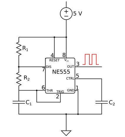
- Pin 8 – Power supply pin;
- Pin 1 – Connection to the ground;
- Pin 3 – Output pin: it can be in either a high or low state;
- Pin 2 – Active low trigger – it controls the timer, starting it when its voltage is lower than one-third of the supply voltage, and setting pin 3 to high;
- Pin 6 – Threshold pin. When the voltage on pin 6 reaches two-thirds of the supply, pin 3 is set to low, and the cycle ends;
- Pin 7 – Also known as the discharge, this allows the discharge of the capacitor that controls the timings of the cycle;
- Pin 5 – Or the control. When connected to a capacitor ( in the diagram, with a usual value of around 10 nF) and the ground, work to even out the noise of the supply; and
- Pin 4 – The reset pin acts as an active low trigger. When connected to the supply, the 555 can operate, but if the voltage on 4 is low, a trigger from 2 is required to restart the cycle.
The 555 astable mode
In the astable mode, the output of a 555 chip remains in the state high for seconds and in the state low for seconds.
These values are controlled by the values of two resistors and a capacitor connected to the 555 (, , and in the diagram). If you need to find out the values of those components, use our capacitor code calculator and resistor color code calculator.
How does a 555 timer work in astable mode
Assume that the chip starts with pin 3 in the high state.
-
At pin 7, discharge is open, and so the current flows through and , charging :
- The voltage on pin 2 and pin 6 increases.
-
As soon as the voltage on pin 6 reaches the threshold of 2/3 of the supply, the output on pin 3 changes to low:
- This causes pin 7 to connect to the ground.
-
discharges through and pin 7:
- The voltage on pins 2 and 6 decreases.
- Pin 2 is triggered when the voltage becomes smaller than 1/3 of the supply, changing the state of pin 3 to high and opening pin 7.
The cycle then repeats, until pin 4, the reset, is triggered.
How does the 555 timer calculator and N555 duty cycle calculator work
The values of and are respectively defined as:
The duration of an entire cycle is given by , and its inverse is the frequency, .
The duty cycle of a 555 is the percentage of the total time that a cycle spends in the high state:
The duty cycle can never be smaller than 50%: in that case, the time in the two states would be the same, corresponding to a charge and discharge of the capacitor on the same resistor: should be , and pin 7 would be connected to the power supply directly, damaging the chip.
The 555 monostable mode
The picture below shows the configuration of a 555 monostable mode circuit. It looks similar to the one we just saw for the astable mode, so let's focus on the differences!
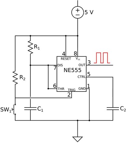
When used in the monostable mode, the 555:
- Pin 6 (the threshold) – Directly connected to pin 7; and
- Pin 2 (the low trigger) – Connected to the power supply through a resistance () with a fixed value (usually ).
Operations of the 555 in the monostable mode
The monostable mode of the 555 IC permits a single stable output state: low. The stable state is obtained when the button switch is unpressed.
In this configuration, pin 2, connected to the supply, is not triggered (remember? It is an active low trigger).
Now, let's press the button and see what happens:
-
is pressed, shorting the supply to the ground:
-
The voltage on pin 2 drops to near null values, and the output switches from low to high; and
-
Pin 7 is disconnected from the ground, thanks to the trigger. The capacitor starts charging.
-
-
Pin 6 measures the voltage across . When it reaches 2/3 of the power supply value, it prompts the output on pin 3 to switch back to low:
- Pin 7 is shorted to the ground again, allowing to discharge.
The original state is now restored, and pressing the button again will restart the cycle.
How does the 555 pulse calculator work?
In the 555 monostable mode, the duration of the pulse, i.e., the interval in which the output on pin 3 is set to high, depends on the charging time of the capacitor . The values of the capacitance and resistance, and , respectively, determine the duration with the formula:
Simple, right?
Testing our 555 timer calculator
Let's say you need to send a ping with your sonar to communicate with an American submarine, but . That's the perfect use of the monostable mode of the 555 IC!
We want a second pulse. We have already found a resistor, so let's just input the data into the calculator for the monostable mode.
The capacitor we should use is a 40 μF one!
If you need to build a blinker, the astable mode is your best choice.
Let's say we want an LED to stay on for 2/3 of a second and off for 1/3. We can use the same resistance values for both and , . Now, we can input the time values. Remember that must be the longer of the two times: and .
The capacitor we need has value . The duty cycle for such configuration is .
If you are working on your electronics project, you may be interested in some other calculators:
FAQs
What are the uses of an NE555?
An NE555 is a versatile chip. You can use it in multiple ways, but most commonly, you will need it when your projects require a timer or a delay. By varying the values of a few electronic components, it is possible to tune the timing of an NE555. Calculate their values on omnicalculator.com
What is the maximum frequency of an NE555?
The NE555 can oscillate at most at 2 MHz. It means that you can have a period of just half a microsecond.
In which modes can you operate an NE555?
You can operate an NE555 chip in three modes: monostable, bistable, and astable. In the monostable mode, there is a single stable state in which the chip returns in a given time after each reset.
In the bistable mode, the stable states are two, and a trigger is required to move the chip between them. The astable mode is probably the most common. In it, the chip oscillates between two stable states with a characteristic time.
What is the difference between NE555 and LM555?
There is no difference between NE555 and LM555. Actually, every 555-type chip operates in the same way; only the internal characteristic and the manufacturer vary. There may be a slight change in behavior, but the final result is the same. You can use the NE555 calculator at omnicalculator.com for all of them!