
Welcome to the high pass filter calculator. If you want to remove some low-frequency noise or you're trying to get more treble, you've come to the right place. Together, we'll learn:
- What a high-pass filter is;
- The different types of high-pass filter circuits;
- Passive high-pass filters and active high-pass filters;
- How to tell high-pass and low-pass filters apart; and
- How capacitors can be used in high-pass filters.
How do I use the high-pass filter calculator?
Using the high-pass filter calculator is easy! Here's how:
-
Select the filter type you're designing. The high-pass filter calculator covers the following filter types:
-
RC high-pass filter;
-
RL high-pass filter;
-
Non-inverting op-amp high-pass filter; and
-
Inverting op-amp high-pass filter.
-
-
Input the values for which you are designing. The passive RC and RL filters (both RLC circuits) let you fine-tune the component values and the desired cutoff frequency, while the active (op-amp) filters also let you adjust the gain on your output.
Keep reading if you want to learn how they work!
💡 The high-pass filter calculator lets you enter whatever values you know, and it will calculate the other values for you. It adjusts its equations according to your choice of filter type.
What is a high-pass filter?
A high-pass filter is an electronic circuit that removes low-frequency components from a given AC signal. In other words, it blocks low frequencies and lets high frequencies pass through it. That's why we call it a "high-pass filter".
What does this mean in practice? Take a look at the Bode plot for high-pass filters below.
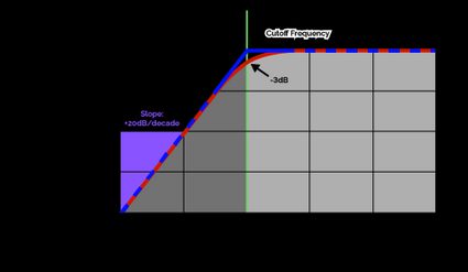
A Bode plot (like the one above) illustrates a circuit's frequency response, which is another word for how it amplifies signals of certain frequencies and damps others. A high-pass filter's frequency response suppresses low-frequency signals, which we can see all the way up to . That frequency is called the cutoff frequency, and it's what defines any high-pass filter:
- Frequencies below are damped; and
- Frequencies above are left untouched.
💡 The Bode plot above has two lines, one representing ideal theoretical filter behavior and the other representing real-world filter behavior. Ideal filters would slope straight down at . For real-world filters, the cutoff frequency is the frequency at which a signal is damped to .
The slope at which the frequency response drops for increasingly low frequencies is . This means that every time the frequency is reduced by a factor of 10, the amplitude is reduced by 20 decibels. This slope is made even steeper if the order of the filter is increased: first-order filters have a 20-decibel slope, second-order filters slope at 40 decibels, third-order descends at 60, etc.
Real-world signals rarely consist of just one frequency, and that's partly why we need high-pass filters in signal-handling circuits. Here's how a high-pass filter affects signals comprised of more than one frequency:
Different high-pass filters — passive vs. active high-pass filters
There are two main categories of high-pass filters:
- Passive high-pass filters exclusively use passive components (which are resistors, capacitors and inductors). The two common passive high-pass filters are RC high-pass filters and RL high-pass filters.
- Active high-pass filters use some active component, typically an operational amplifier (or "op-amp"). Thanks to their adjustable gains, they can be modified more than passive filters.
RC high-pass filter
The RC high-pass filter consists of a resistor and a capacitor in the configuration shown below.

It's probably the most well-known yet basic high-pass filter, partly thanks to the easy formula for its cutoff frequency:
The RC high-pass filter works thanks to its capacitor. A capacitor's impedance decreases with frequency, making it act like a short-circuit for high-frequency signals. Inversely, a capacitor acts as an open circuit for low frequencies.
where is the unit imaginary number.
Thanks to this frequency-dependent impedance, we can use capacitors for high-pass filters.
💡 Engineers frequently bridge their constant voltage rails to ground with capacitors, which act as high-pass filters and remove any shakiness in the voltage supply.
RL high-pass filter
The RL high-pass filter uses an inductor and a resistor in the configuration below:

Its cutoff frequency is also very simple to calculate:
An inductor acts the opposite way a capacitor does: An inductor becomes a short-circuit for low-frequency signals and an open circuit for high frequencies. Because of this, any low-frequency components of pass through the inductor, but high-frequency components are blocked. Instead, high-frequency components must travel through the load at instead. Here is the equation for the impedance of an inductor:
Inverting op-amp high-pass filter
The inverting op-amp high-pass filter is an active filter that incorporates an operational amplifier (op-amp). The op-amp feeds back into itself with the feedback resistor , with the high-pass filtering performed by the capacitor . It's designed as follows:

Its cutoff frequency is calculated much like the RC filter's but with the feedback resistor .
And the gain introduced by the op-amp is calculated with
See that minus sign in the equation for ? It means that we're flipping the signal around the time-axis, or in more technical terms, we're introducing a 180° phase shift. If this behavior is undesirable, then head on over to the next section on NON-inverting op-amp high-pass filters.
Non-inverting op-amp high-pass-filter
The non-inverting op-amp high-pass filter is more complicated than its inverting sibling, but it has the useful property of not inverting the input. We connect an RC high-pass filter to the negative input of the op-amp and create a feedback loop between the op-amp's output and the op-amp's positive input. See its circuit diagram below:

Because the only filtering is done by the passive RC circuit at , we can calculate the filter's cutoff frequency by:
And we can calculate (the gain from to ) with:
Note that is positive, but also that , as resistance can never be negative.
FAQs
What components do I need for a 1 kHz high-pass filter?
To build an RC high-pass filter with a cutoff frequency of 1 kHz, use a 3.3kΩ resistor and a 47nF capacitor. Such a high-pass filter circuit will have a cutoff frequency of precisely.
fc = 1 / (2π × 3.3 kΩ × 47 nF) = 1.0261 kHz
Remember to keep components' tolerances in mind — consider measuring them with a multimeter!
How do I tell a high-pass filter from a low-pass filter?
You can differentiate high-pass vs. low-pass filters in a few ways.
- Analyze the circuit. Using techniques like Laplacian transformation, calculate the frequency-dependent impedance of each component and determine the filter's frequency response.
- Test it with signals. Feed waveforms of varying frequencies to the circuit and monitor the amplitudes at the outputs.
- Compare the circuit to known filter layouts. If you see your circuit matches a well-known filter design, you can guess what filter type it is.
How do I build a high-pass filter?
To build a high-pass filter, follow these easy steps:
- Select a suitable filter type (RC, RL, op-amp, etc.).
- Determine your desired cutoff frequency, fc.
- Calculate the components' values based on the above choices. The equations are dependent on the filter type you selected.
If you need more help, come to omnicalculator.com's high-pass filter calculator!