
Welcome to Omni's low pass filter calculator. Whether you're designing an entire sound system complete with a bass boost, or just want to remove high-frequency noise, the low-pass filter calculator can help you create the perfect low-pass filter circuit for your needs. Read on to learn:
- What a low-pass filter is;
- The difference between passive and active low-pass filters; and
- Whether inductors (that offer inductive reactance) can be used for low-pass filters.
How do I use the low-pass filter calculator?
Using the low-pass filter calculator is easy! Here's how:
-
Select the filter type you're designing. Based on this choice, the low-pass filter calculator can magically transform into an RC low-pass filter calculator, an op-amp low-pass filter calculator, and others. We offer the following filter types:
- An RC low-pass filter;
- An RL low-pass filter;
- An non-inverting op-amp low-pass filter; and
- An inverting op-amp low-pass filter.
-
Input the values you are using. The passive (RC and RL) filters allow component values and the desired cutoff frequency. To the active (op-amp) filters, you can also add a gain to your AC signal. Read on if you want to learn how they work!
💡 The low-pass filter calculator is omnidirectional. You can enter whatever values you know and the calculator will work out the rest according to the selected filter type.
What is a low-pass filter?
A low-pass filter is an electronic circuit that removes higher-frequency components from a given AC signal. In other words, it blocks high frequencies and lets low frequencies pass — hence the name "low-pass filter".
Let's illustrate a low-pass filter's frequency response (a fancy word for how a filter amplifies or dampens signals of certain frequencies). Take a look at the typical Bode plot for a low-pass filter below:
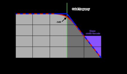
In the graphic above, we can see that a low-pass filter's frequency response is relatively flat up to , after which it descends quickly. That point is called the cutoff frequency and it's the defining parameter of a low-pass filter.
💡 The low-pass filter has an ideal (theoretical) and a real (practical) version. Ideally, the cutoff frequency marks the sharp transition point between the Bode plot's flat and sloped regions. In reality, that transition is gradual, and instead marks where the filter's frequency response hits the mark.
Past the cutoff frequency, the filter's frequency response drops at a slope of 20 decibels per decade — or, equivalently, the amplitude of a signal passing through the filter decreases by a factor of 10 for every tenfold increase in the signal's frequency.
💡 Note, that the explanation above is mostly true for all low-pass filters, even though the ones we discuss in this article are only first-order filters. The only difference between first-order and higher-order filters (such as RLC circuits) is that their high-frequency signal response drops at a higher rate than 20 decibels per decade.
When dealing with signals containing more than one frequency, a low-pass filter will remove the high-frequency components while leaving low-frequency components untouched. For audio systems, this would typically mean the treble is dampened, and the bass is seemingly amplified.
Different types of low-pass filters — passive vs. active low-pass filters
While all low-pass filters perform the same function, many different low-pass filter circuits exist. They are split into two categories, passive and active, and this dichotomy can be categorized further:
- Passive low-pass filters are built with only the three linear passive components: the resistor, the capacitor, and the inductor. They include:
- RC low-pass filters; and
- RL low-pass filters.
- Active low-pass filters can be built with active components, most notably the operational amplifier (or op-amp). They include:
- Inverting op-amp low-pass filters; and
- Non-inverting op-amp low-pass filters.
The RC low-pass filter
The RC low-pass filter consists of a resistor (with resistance ) and a capacitor (with capacitance ) in the configuration shown below:

The RC low-pass filter is probably the most well-known passive low-pass filter. It is simple to design and build thanks to the simple formula for its cutoff frequency :
The RC low-pass filter takes advantage of the reactive properties of the capacitor, whose impedance decreases as the signal frequency increases:
Higher frequencies can easily pass through the capacitor and skip the load at ; lower frequencies are blocked from flowing through the capacitor and must instead travel through the output terminals. In this way, lower frequencies are delivered to the load, and higher frequencies are filtered out.
The RL low-pass filter
We haven't seen any inductors yet, but don't worry — inductors can be used for a low-pass filter just as easily as capacitors and resistors! Similar to the RC filter, the RL low-pass filter is another passive filter, and is constructed with a resistor and an inductor in this configuration:

Its cutoff frequency can be determined with this formula:
Inductors behave in the opposite way to capacitors — their impedance grows with the frequency of the signal it's conducting:
As a result, the inductor in the RL low-pass filter blocks higher frequencies from ever reaching , while allowing lower frequencies to pass through the inductor and reach the output.
The inverting op-amp low-pass filter
The inverting op-amp low-pass filter is an active filter, meaning it doesn't use just passive components (resistors, capacitors, and inductors). This particular filter incorporates an operational amplifier (op-amp) that feeds back into itself with the feedback resistor and capacitor . It's designed as follows:

Lucky for us, the formula for the cutoff frequency is simple:
Because op-amps are powered by an external voltage source that is independent of the input signal, the inverting op-amp low-pass filter introduces a gain by which the input signal will be multiplied to obtain :
It's important to note that the inverting op-amp low-pass filter's gain is negative. Therefore, your output signal will be flipped to be exactly 180° out of phase with the input signal — that's why it's called an "inverting filter". For some circuits (like audio systems) this effect doesn't matter much (as speakers don't care about polarity) but in other applications, the flip must be kept in mind. If you want to avoid this flip, then jump on over to the section on NON-inverting op-amp low-pass filters.
💡 Remember that op-amps have a maximum DC voltage that can be supplied to their rails — consult the component's datasheet to find it. Whatever its value, this DC supply voltage limits the output of your op-amp filters. If your gain is too large, or you supply with signals that are too large, your output will be distorted.
The non-inverting op-amp low-pass filter
The non-inverting op-amp low-pass filter doesn't flip the signal like the inverting op-amp filter does — its output retains the polarity of its input .

The formula for its cutoff frequency is:
As an active filter, the non-inverting op-amp low-pass filter also introduces a gain :
Because of the in , the gain will always be at least , i.e. . So, if you were planning on reducing the amplitude of your signal with , you might want to consider the inverting op-amp low-pass filter instead.
FAQs
What does a low-pass filter do? Why use a low-pass filter?
Low-pass filters block high frequencies and admit low frequencies. With suitable cutoff frequencies, low-pass filters can be applied to:
- Sound engineering, specifically amplifier design;
- Noise reduction (useful in telecommunications); and
- Biomedical devices, such as vital sign monitoring and pacemakers.
What is the cutoff frequency of a low-pass filter?
A low-pass filter's cutoff frequency, fc, is the frequency at which the filter's gain is −3dB. Frequencies lower than the cutoff frequency are admitted through the filter, and higher frequencies are blocked. For the typical RC low-pass filter, fc = 1 / (2πRC).
How do I build a low-pass filter?
To build a low-pass filter, follow these easy steps:
- Select a suitable filter type (RC, RL, op-amp, etc.).
- Determine your desired cutoff frequency, fc.
- Calculate the components' values based on the above.
What components do I need for a 1 kHz low-pass filter?
You can build an RC low-pass filter with a cutoff frequency of 1 kHz using a 3.3 kΩ resistor and a 47 nF capacitor (which are standard resistor and capacitor values). Such a circuit will deliver an exact cutoff frequency of
fc = 1 / (2π × 3.3 kΩ × 47 nF) = 1.0261 kHz
Remember to keep components' tolerances in mind — consider measuring them with a multimeter!