What Is a Logic Gate?
A logic gate is represented using standardized logic gate symbols, which visually describe how inputs are processed. For example, logical negation (NOT) is represented by a triangle, following the ANSI convention, because it is implemented by a simple transistor mounted as an inverter. This is why the inverter logic gate, also known as a NOT gate logic circuit, has only one input.
Some logic gates, including AND and OR, require at least two inputs. The logic gate AND gate outputs a 1 only when all inputs are 1, while other gates follow different rules, as described in the truth tables of all logic gates.
To make these differences concrete, the following table summarizes the most common logic gates, their symbols, Boolean expressions, and output behavior.
Type | ANSI symbol | Boolean algebra between A and B | Truth table |
|---|---|---|---|
Buffer |  | ||
NOT (inverter) |  | or | |
AND |  | or | |
OR |  | or | |
NAND |  | or | |
NOR |  | or | |
XOR |  | or | |
NXOR |  | or | |
IMPLY |  | or | |
NIMPLY |  | or |
The truth tables show how each logic gate responds to every possible input combination, forming the foundation for more complex digital circuits.
All of these operations are rooted in Boolean logic, which is explained in more detail in our related article: “What Is Boolean Algebra?”
Let's see how to use logic gates to make a counter. A DC (direct current) generator powers the circuit shown below, while the clock signal gives the time base. The 74LS107D circuits are simple Schottky diode-based inverters that illustrate the role of an inverter in logic gates. They detect every change of state (from 0 to 1 or from 1 to 0) in their input and send a signal of 1 each time a change occurs (trigger function). This behavior is typical of an inverter logic gate, also known as a NOT gate logic circuit, and is commonly shown using standard logic gate symbols.
The principle of the DCD_HEX digital display at the top right is simple. Based on the four-bit binary word it receives at its input, it displays the decimal value of the corresponding number (e.g., 0110 = 0x2³ + 1x2² + 1x2 + 0x2⁰ = 6) by lighting up the segments of a seven-segment display.
 |
To understand the operation of this circuit, assume the inputs are initially 0 and proceed from left to right in the diagram. Each emission of a slot by the generator produces an alternation from 0 to 1, then from 1 to 0, which triggers a signal from the inverter circuits.
Using the truth tables of all the logic gates in the circuit, one can determine the state (0 or 1) of the four input bits of the display circuit for each of the four slots emitted in sequence. These truth tables are often paired with logic and Venn diagrams to visually represent logical relationships.
The comparator circuit is hardly any more difficult to understand. It is enough to construct the truth table of the four proposed outputs based on the input values (0 or 1) of A and B. This comparison logic relies on the same principles that define what a logic gate is, regardless of circuit complexity. The notation “!=” means ≠.
 |
If you want to practice building them yourself, this guide on “How to Make a Truth Table” walks through the process step by step.
The following circuit allows arithmetic operations to be performed in base 2. It takes two 2-bit words as inputs, for example, A and B. The unit bit is denoted A[0] for A and B[0] for B, while the most significant bit is coded A[1] and B[1]. At this stage, the circuit illustrates how multiple instances of a logic gate operate in conjunction with one another.
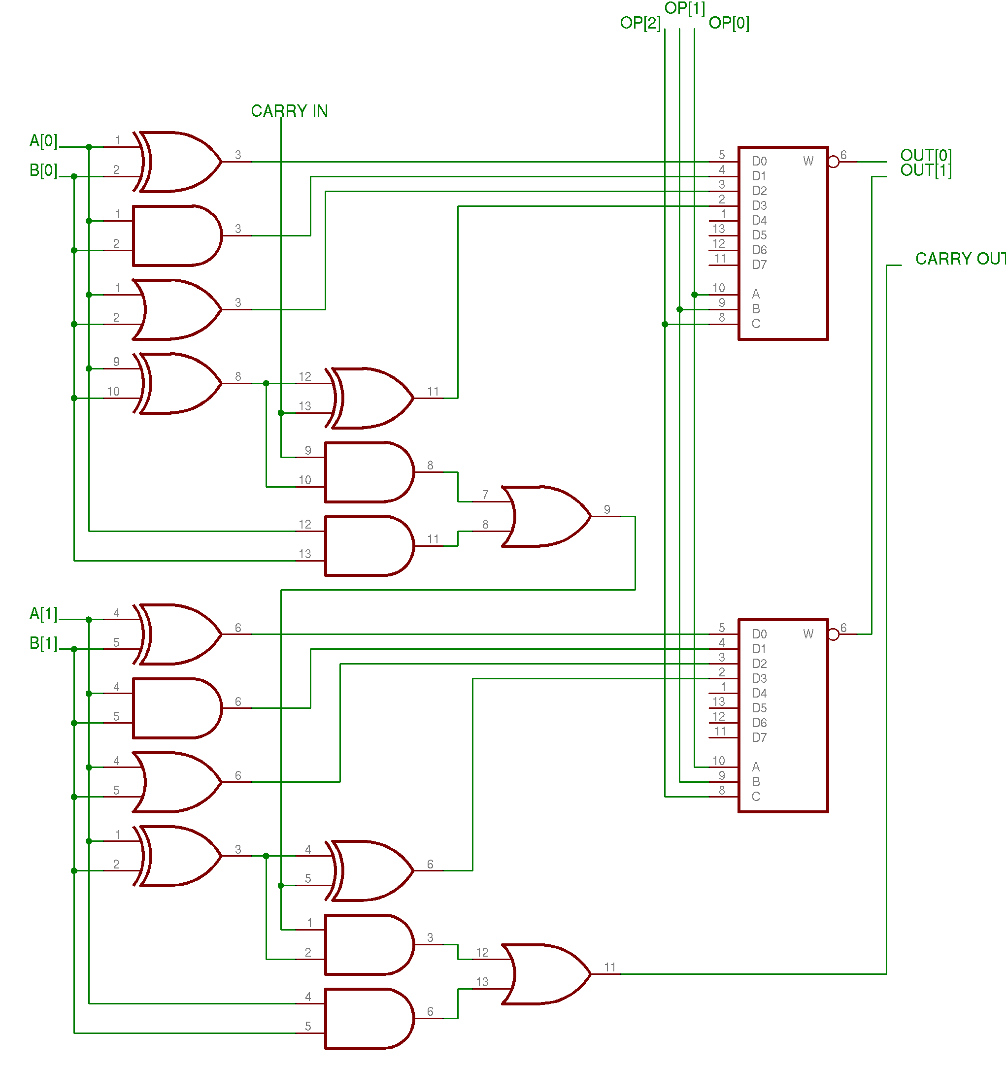 |
The inputs A and B are sent to the four logic gates on the left of the diagram. From top to bottom, the gates are XOR, AND, OR, and XOR. This configuration includes both an XOR logic gate and an AND logic gate, forming part of an XOR gate logic circuit used in arithmetic operations. The final XOR gate serves as the input stage of an adder circuit, while related designs may also use a NAND gate logic circuit for efficiency.
In addition to inputs A and B, the circuit considers a possible hold resulting from a previous operation (CARRY IN). Similarly, if the circuit performs an operation that results in an overflow, it outputs a carry-out (CARRY OUT) bit. In the stack of a microprocessor, these special bits are stored in a state register, reinforcing what the logic gate is as a fundamental building block of computation.
Each bit is finally sequenced by a multiplexer (the two rectangular blocks to the right of the diagram) to form the result. The nature of the function to be performed is given by the OP signal, encoded on three bits by a control unit:
OP = 000 → XOR;OP = 001 → AND;OP = 010 → OR; andOP = 011 → Addition.
This logic relies heavily on the logic gates, including the XOR gate, and other standard gate combinations working together.