Have fun designing your own J-pole antenna for any band with our J-pole antenna calculator. It allows you to build a J-pole antenna for the chosen frequency band. Perhaps you are curious about how to build a copper J-pole antenna, so you have come to the right place.
The J-pole antenna (whose shape resembles the letter J) is now a popular form of vertical antenna, widely used for everything from mobile radio communications to amateur radio and much more. The J-pole calculator below will give you an excellent initial geometry, but feel free to build your own antenna and modify the spacing between the elements, materials, and other details to fine-tune the antenna to suit your needs.
You will also learn what is the velocity factor and how to prepare for J-pole antenna mounting.
What is a J-pole antenna?
J-pole antenna (also known as J antenna) owes its name to its shape resembling the letter J. It was invented in 1909 by Hans Beggerow for use in Zeppelin airships. Typically, J antennas are used in shortwave frequency bands (up to 30 MHz), while radio waves can be used for very long-distance (transcontinental) communications. If you want to know more about frequency, check our frequency calculator.
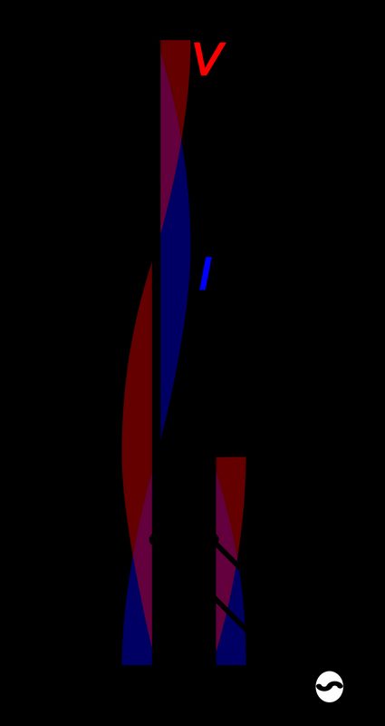
The J-pole antennas are designed for radio services, maritime communications, international shortwave broadcasting, and worldwide amateur radio. The J-pole antenna is effectively a half-wave antenna that is fed at one end – this is the point where the voltage is maximum, and the current is minimum. There is a very high impedance at this point, which needs to be reduced to a more convenient level using a quarter-wave balanced feed.
How does a J-pole antenna work?
The J-pole antenna can be compared to a half-wave dipole fed from the end. Just as a magnet has two magnetic poles, north and south, so in a dipole, we have two electrical poles, positive and negative. Being a half-wave, there are always two opposite poles at the ends of each half-cycle. Hence the name 'dipole' and each half-wave antenna is, in fact, a dipole. You can calculate its length using dipole antenna calculator.
In the case of a full wave, the wave will merge if you imagine placing them on top of each other. The feed to the dipole is usually at the center where the cable impedance is about 70 Ω, but you can also feed the dipole anywhere along the beam. This point of a half-wave high-impedance antenna must be matched to 50 Ω in the quarter-wave (λ/4) matching section.
What is the velocity factor?
The velocity factor () is a parameter describing the speed at which the signal travels in comparison to that of a signal traveling in free space. If the signal travels at the speed of light, its velocity factor would be 1.0, and for one traveling at half the speed of light, it would be 0.5. For example, the velocity factor of a copper wire is set by default to 0.96. You can also calculate the velocity factor of the cable as the reciprocal of the square root of the dielectric constant :
The speed factor of the cable is an important parameter, so you can always find it in the data sheets of the coaxial feeder. Otherwise, check out the dielectric constant of the material used in your coaxial cable and type it into the J-pole antenna calculator using the Additional parameters field.
J-Pole antenna design
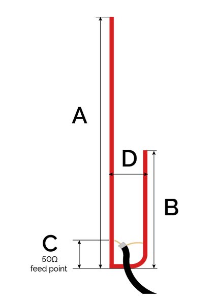
Using the J-pole antenna calculator to build an antenna for a given frequency, you should find the dimensions of the following elements:
-
Long section dimension (A) - overall length of the antenna, it could be described as .
-
Short section dimension (B) – quarter wave matching section in which the centrally fed half-wave antenna is matched to the 50Ω coaxial cable, its length is approximately .
-
Feed point dimension (C) – feed point 50Ω where antenna tuning occurs can be found once you have built the antenna to the correct dimensions. Approximate formula is .
-
Spacing dimension (D) – you should include spacing between elements; however, it is not a critical value. You may set it as 45 mm for every 2 meters or use the formula .
How to use J-pole antenna calculator?
In this short tutorial, learn how to use a J-pole antenna calculator to find the optimal J-pole antenna design:
-
Enter the current frequency of your J-pole antenna.
-
Choose the velocity factor of copper wire or other materials or enter the material's dielectric constant (in
Additional parametersmode). -
Our J-pole calculator will find for you the dimensions of the different antenna areas.
Remember that this J-pole calculator will give you a good starting point, although element spacing, velocity factor, and other differences will affect the performance of your J-pole antenna.
FAQs
Are J-pole antennas directional?
No, J-pole antennas are not directional. They belong to the class of antennas where the radio power radiates equally in all directions perpendicular to the azimuth axis, and the power varies with the angle. You can imagine this radiation pattern in three dimensions as a doughnut shape.
How can I mount a J-pole antenna?
Once you have found the J-pole antenna design and built it up, you can mount the antenna on a chimney or roof in a few steps:
-
Use antenna mounting accessories to put the antenna on your chimney or roof. Remember to keep your antenna at least six feet from or above metal objects.
-
Use a choke ballon to help keep any radio frequency energy from traveling back down the feed line. A choke ballon could be as simple as a coil of coax near the feed point.
-
Create a drip loop to help keep the stress off the connector.
-
Seal everything up with electrical tape.
-
Do not use a ground plane for your J-pole.
How can I build a copper 2-meter J-pole antenna?
If you are interested in how to build a copper J-pole antenna, follow these instructions:
-
Choose 145 MHz from the 2-meter frequency band, note the speed of light c, and calculate the wavelength λ from the formula λ = c/f = (299,792,458 m/s) / (145,000,000 1/s) = 2.07 m.
-
Check the velocity factor for bare copper, which is 0.96.
-
Calculate the four dimensions of your J-pole antenna:
-
A is 0.75 × 2.07 m × 0.96 = 148.9 cm;
-
B is (2.07 m / 4) × 0.96 = 49.6 cm;
-
C is (2.07 m / 50) × 0.96 = 5 cm; and
-
D is (0.045 × 2.07 m) / 2 = 4.7 cm.
-
How do I find the overall length A if frequency is 100 MHz?
The dimension A for copper wire is 215.9 cm. The wavelength at 100 MHz is equal to (299,792,458 m/s) / (100,000,000 1/s) = 3.00 m. The overall length with velocity factor 0.96 will be 0.75 × 3.00 m × 0.96 = 215.9 cm.