RC Filter Calculator
Table of contents
Calculating RC low-pass filterCalculating RC high-pass filterCalculating RC band-pass filter calculatorHow to use this online RC filter calculator?Other filter circuit calculatorsFAQsThis online RC filter calculator is a quick and easy tool to help you design an RC filter for low-pass or high-pass filter circuits. With just a couple of inputs, this tool will calculate the cutoff frequency for an RC filter circuit. Experts can even use this calculator to calculate RC band pass filter circuits!
A filter circuit is a circuit that will help you filter out undesired frequencies from the input signal. Depending on whether the circuit can remove high frequencies or low frequencies from the input signal, we call it a low-pass or a high-pass filter circuit. The following article briefly describes how to use an RC circuit as a low-pass or a high-pass filter.
Calculating RC low-pass filter
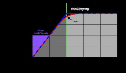
A low-pass filter calculator removes high-frequency noise from an input signal, allowing only low frequencies to pass through. The characteristic cutoff frequency is the frequency above which all signals are blocked from passage.

In practice, the drop in gain is not sharp - instead, the gain drops gradually. Hence, the cutoff frequency is the frequency at which the gain drops to -3 dB.
The RC filter circuit contains a resistor and a capacitor. A capacitor's impedance is inversely proportional to the signal frequency, while a resistor's impedance is independent of the signal frequency. For a low-pass filter, the capacitor is connected parallel to the load, while the resistor is in series with the load.

The bridge parallel to the load remains disconnected for low-frequency signals since the capacitor impedes any current from passing through. So, the low-frequency signals pass through the circuit to the output without deterrence.
On the other hand, high-frequency signals pass through the capacitor with negligible impedance, shorting the circuit before the output connection point. Thus, high frequencies are blocked from passing through.
The formula to calculate the cutoff frequency of the RC filter is:
where:
-
- The cutoff frequency of the RC filter;
-
- The resistance of the resistor; and
-
- The capacitance of the capacitor.
Calculating RC high-pass filter
A high-pass filter blocks low-frequency noise in the input signal, allowing only high-frequency signals to pass through.
Since the capacitor's impedance is inversely proportional to the signal frequency, it is connected in series with the load for a high-pass filter. This blocks low frequencies from reaching the load but allows high frequencies to pass unhindered.

Calculating the RC high pass filter's cutoff frequency uses the same formula we've seen in the previous section:
Calculating RC band-pass filter calculator
A band-pass filter lets a specific range of frequencies through while blocking the others. It is a circuit that combines a low-pass and high-pass filter. To calculate an RC band-pass filter, follow these steps:
-
Calculate an RC low-pass filter that blocks all frequencies below the desired range.
-
Calculate an RC high-pass filter that blocks all frequencies above the desired range.
-
Use them in the appropriate combination.
How to use this online RC filter calculator?
Our RC filter calculator is simple to use:
-
Input the resistance of the resistor.
-
Enter the capacitance of the capacitor.
-
The RC filter calculator will automatically determine the cutoff frequency of the filter circuit.
If you're designing a circuit with a cutoff frequency in mind, you can enter the cutoff frequency and either the resistance or the capacitance to find the remaining variable. This online RC filter calculator is robust - play around till you arrive at satisfactory values.
Other filter circuit calculators
We have other filter circuit calculators for you to explore:
How do you calculate the cutoff frequency of an RC filter?
To calculate the cutoff frequency of an RC filter circuit, follow these steps:
-
Multiply the resistance of the resistor (in Ohms) with the capacitance of the capacitor (in Farads).
-
Multiply the result with
2π. -
Take the reciprocal of this product to find the cutoff frequency of the RC filter.
What inductor do I need for a 1 kHz RC high-pass filter?
To design an RC high-pass filter with a 1 kHz cutoff frequency using a standard capacitor of 47 nF, follow these steps:
-
Multiply the cutoff frequency (in Hz) with the capacitance (in Farads):
1000 Hz × 47×10-9 F = 47×10-6 -
Multiply this result with 2π and take the reciprocal of the product to obtain the resistance (in Ohms):
R = 1/(2π × 47×10-6) = 3.386×10³ Ω = 3.386 kΩ -
Verify this result using our RC filter calculator.